Behavior Modeling Overview
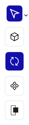
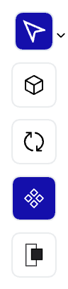
Dalus provides a complete canvas for modeling dynamic system behavior with executable elements. The left sidebar shows your behavior elements, making it easy to navigate between actions and states in your system.
What are Action Nodes
Action nodes are executable elements that perform computations, process data, or trigger system behaviors. Each action contains a script that can read input variables, perform calculations, and produce output variables. Actions connect to other actions through signal edges to create complex behavior flows.Creating Action Nodes
Create action nodes using the toolbar on the left side of the canvas. Click the Action button (or pressA) to add new actions to your model. You can name actions by editing their labels directly.
Action Properties and Scripts
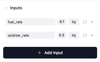
When you select an action, the right sidebar shows all its properties including input/output variables, script name, and execution settings. Each action contains:- Script Editor: Write Python code that defines the action’s behavior
- Input Variables: Data inputs that the action receives from other actions
- Output Variables: Data outputs that the action produces for other actions
- Notes: Additional documentation about the action’s purpose
Script Editor Interface
The script editor provides a comprehensive environment for writing and executing Python code. Access all variables in your model through the built-in search functionality.Writing Python Scripts
Write Python code directly in the editor to define your action’s behavior. The editor provides syntax highlighting and supports standard Python libraries.Using Variables in Scripts
Search for and copy variable IDs from anywhere in your model to use them in your scripts. Click the Variables button to access the search interface.Running Scripts
Execute your scripts directly from the editor using the Run button. Monitor execution status and view outputs in the console below.Data Visualizations
Actions can generate and display data visualizations including tables, line charts, and pie charts. These visualizations automatically appear in the right sidebar after script execution and help you analyze your action’s outputs. Available visualization types:- Tables: Display structured data in tabular format with sortable columns
- Line Charts: Show data trends and relationships over continuous variables
- Pie Charts: Visualize proportional data and categorical distributions
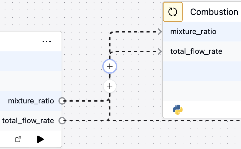
Creating Signal Edges
Signal edges connect action nodes to transfer data between them. They represent the flow of information (variables) from one action’s outputs to another action’s inputs. To create signal edges:- Click and drag from an output handle on one action
- Connect to an input handle on another action
- The signal edge automatically links the corresponding variables
What are State Nodes
State nodes represent distinct operational modes or conditions of your system. Each state can have associated actions that execute when entering, staying in, or exiting the state. States connect through transition edges to form state machines that control system behavior.Creating State Nodes
Create state nodes using the toolbar on the left side of the canvas. Click the State button (or pressS) to add new states to your model. You can name states by editing their labels directly.
State Properties and Actions
When you select a state, the right sidebar shows all its properties including associated actions and notes. Each state can contain:- Entry Actions: Actions that execute when entering the state
- Do Actions: Actions that execute continuously while in the state
- Exit Actions: Actions that execute when leaving the state
- Notes: Additional documentation about the state’s purpose
Creating Transition Edges
Transition edges connect state nodes to define valid state changes in your system. They represent the paths your system can take between different operational modes.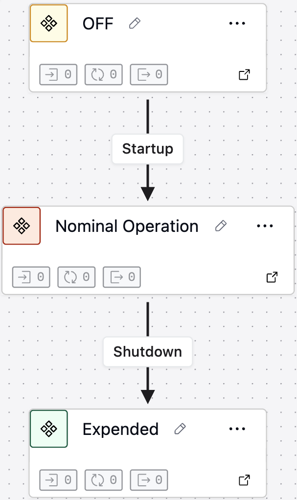
- Click and drag from one state node
- Connect to another state node
- Configure the transition’s trigger effects
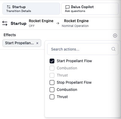
Transition Properties and Effects
When you select a transition, the right sidebar shows its properties including:- Label: Name or description of the transition
- Effects: Actions that execute during the state transition
- Notes: Additional documentation about when and why the transition occurs
State Machine Execution
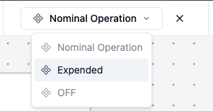
The behavior modeling system supports runtime execution where:- The system starts in an initial state
- Actions execute when transitioning states, triggered using the States Dropdown below:
Coming Soon: Advanced transition control with triggers and guards. Triggers will allow you to specify when state transitions automatically occur based on conditions or events, while guards will define when transitions cannot occur under any circumstances, providing fine-grained control over state machine behavior.
Essential Tips
- Plan Data Flow: Design signal connections before writing action scripts
- Use State Machines: Organize complex behaviors into clear operational modes
- Test Incrementally: Build and test actions individually before connecting them
- Document Behavior: Use notes to explain action purposes and state meanings
- Monitor Execution: Use the simulation features to verify behavior logic