Overview
There are ten fundamental elements in Dalus that serve as the foundational building blocks for complex system modeling.| Element | Purpose |
|---|---|
| Variable | Represents the quantities and units for Part attributes, Action inputs/outputs, and Interface connections. |
| Requirement | Definition of a customer or system-level need. Includes assigned systems, functions, owner(s), and quantitative constraints that determine verification status |
| Part | Structural / spatial / logical unit or block. Can be decomposed indefinitely to build a hierarchical system structure. |
| Port | Attach to Parts to represent an inlet or outlet. |
| State | Represents the different “modes” or states your system can be in; assignable under any Part. |
| Action | Represents the different actions your system can perform; assignable under any Part. |
| Interface | Connect two Ports together to represent physical contact. Interfaces can contain multiple connections, each of which represents a flow of information, mass, energy, or force. |
| Transition | Connect two States together. Defines the conditions under which the transition is triggered and which Actions get executed when triggered. |
| Signal | Connects Actions together to represent a sequence. Propagates output Variables to inputs and triggers the next Action to execute. |
Coming from SysML v1? See the SysML v1 ⇄ SysML v2 ⇄ Dalus mapping.
Variables
A Variable consists of a name, value, and unit (optional). They show up as:- Part attributes (e.g., mass: 200 kg)
- inputs and outputs on Actions (e.g. voltage: 10 V)
- connections inside interfaces, and connection properties (e.g. flow_rate: 8 kg/s, T: 25 C, p: 90 psi)
1 + 2*(43^5), and can also reference other variables by name, i.e. total_mass = mass1 + mass2.
Requirements
A Requirement captures a stakeholder need or obligation that the system must satisfy. Core schema:level– abstraction level of the need (mission, system, subsystem, component)name– short, human-readable titlestatement– the text of the requirement expressed as a shall/should clauseconstraints– a list of quantitative checks such asmass < 100 kg. Each constraint references one Variable, an operator (<,>,=,<=,>=), and a limit (numeric value + optional unit).status– verification state automatically derived from the constraints (e.g., complete when every constraint is true, failed when any constraint is false, in progress when one or more referenced variables lack a value)
Verification
The status of the requirement is determined by the interplay between Constraints, Variables, and Actions:- Constraints, i.e.
mass < 100 kg, evaluate to true or false. Constraints are evaluated continuously as their reference Variable changes, i.e.mass. - A requirement’s status is automatically determined based on its constraints, i.e. complete, failed, etc..
- Actions can set Variables globally using python.
Parts (Physical Decomposition)
- The fundamental structural element in Dalus is the Part. A Part is a self-contained portion of your system, whether hardware or software, that you treat as a black box.
- Parts can be nested indefinitely to capture system decomposition: spatial decomposition for hardware (physical assemblies, sub-assemblies, components) and logical decomposition for software (infrastructure, software layers, services, modules).
Whenever you create a Part, you are drawing a clear system boundary. Boundaries should reduce cognitive load, localise changes, and align with team member ownership/responsibilities. - Part properties are called attributes which are simply Variables that belong to parts.

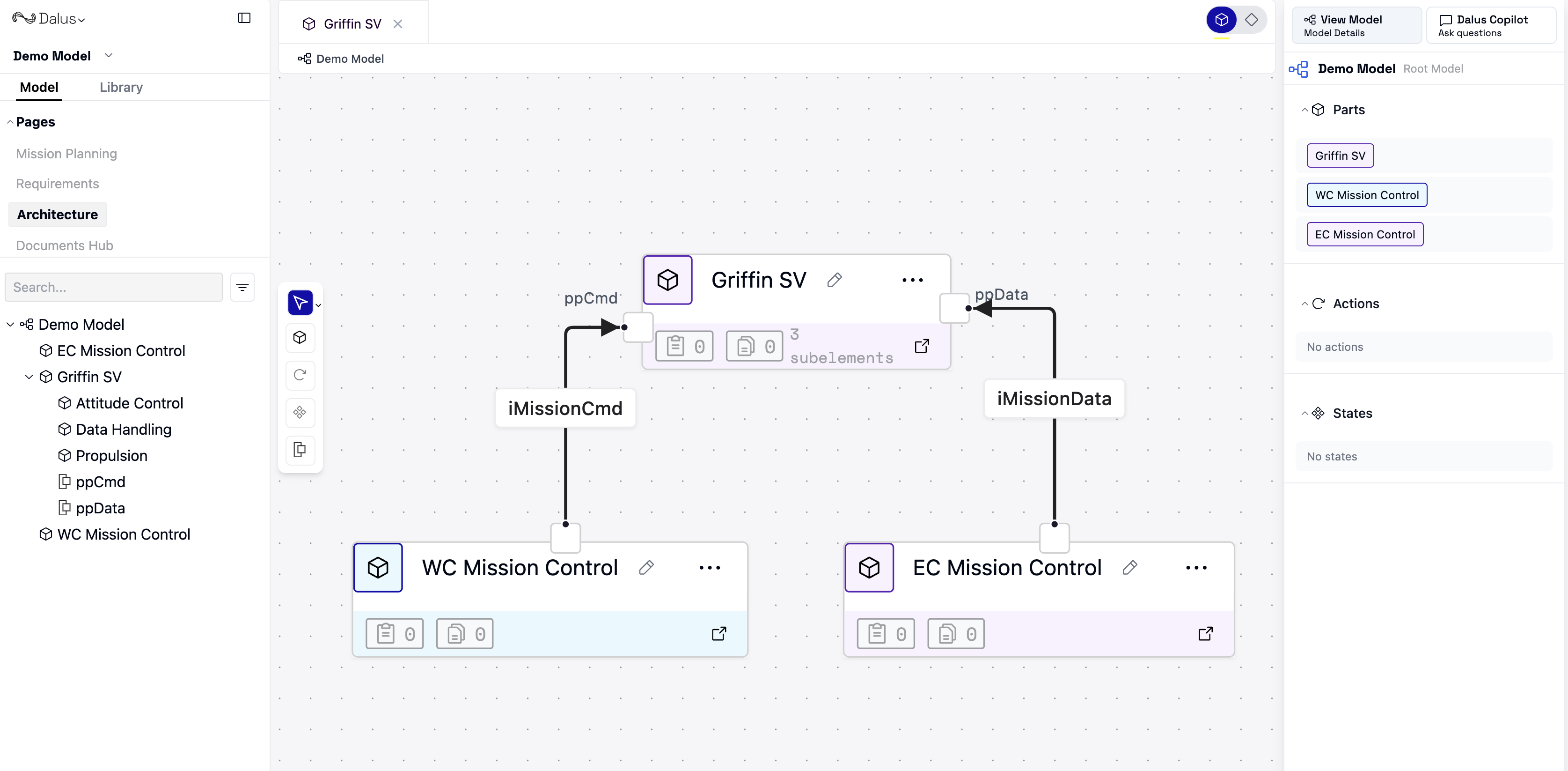
Figure 1. Structural decomposition of the Griffin SV satellite
Ports
Ports are the exposed entry or exit points on a Part’s boundary. They mark where the part interacts with the outside world. By dropping a Port onto a Part in Dalus you are literally poking a hole through the system boundary you established when you created that Part.
Figure 2. Example ports on Griffin SV and their connection to mission control centers
Interfaces
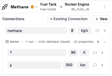
Interfaces define what is actually flowing between Parts through Ports. An Interface itself has a name, and optionally a color, and one interface can consist of multiple Connections, —the individual flows of matter, information, energy, or mechanical load (binding) that actually move between the Parts.Connections
A Connection captures four key fields:| Field | Description |
|---|---|
| Type | Matter, Information, Energy, or Binding |
| Direction | Flow orientation relative to the owning Part (e.g. in, out, both) |
| Subtype | Optional subtype (e.g.) Ethernet, O2 gas, Electrical |
| Variable | The numeric value and unit (e.g. 2 kg/s, 28 V) |
| Properties | (Optional) list of variables to further define the connection (e.g., 128 kHz, 5°C, 85 Pa) |

Figure 3. Interface connecting two Griffin SV subsystems
️Coming Soon: Define Port constraints to limit quantity ranges (e.g., ≤ 10 A), allowed connection types, and permitted flow directions.
States
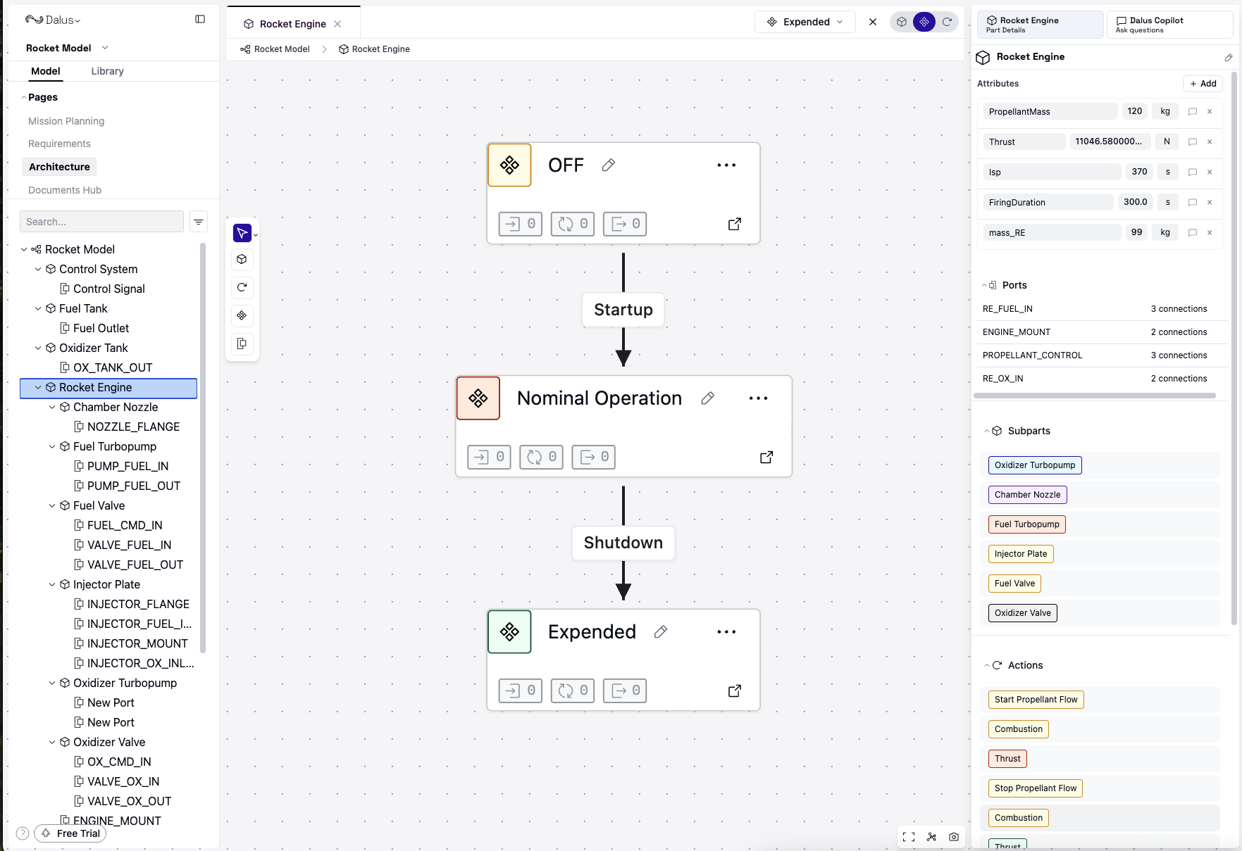
Let’s shift gears a bit. Up until now, we’ve been discussing how to model system structure, and we were fundamentally constrained by space. States mark our shift in this guide to modeling system behavior. A State captures a distinct mode a Part can inhabit at any given time during its lifecycle (e.g., OFF, NOMINAL OPERATION, EXPENDED). To assign a State to a Part, it is simply add it inside that Part.Transitions
A Transition defines what states are allowed to transition to other states, and what happens when the transition occurs. To create a transition, simply connect two states together in the Canvas. When selecting the transition, go to the Right Sidebar to assign a direction and Actions (called transition Effects) to execute when the transition occurs. Transitions can then be manually triggered by you, the modeler, to execute those Actions.️Coming Soon: Specify triggers and guards (boolean conditions) to program when a transition fires.
The transition fires if and only if any trigger is true AND all guards are false.

Figure 4. State machine of 'Rocket Engine'
Actions
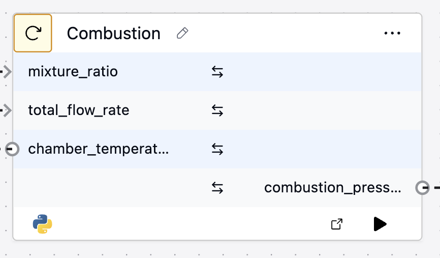
Actions are the functions that a Part performs. Like States, every Action you create shows up as its own node nested under the Part that owns it, keeping behaviour and structure aligned. Each action:- Consumes input variables
- Runs a short Python code snippet to do the work, and
- Produces output variables.

Figure 5. 'Combustion' Action computes combustion pressure and chamber temperature of the Rocket Engine
- description – plain-language summary of what the action does
- success criteria – how you’ll decide the action succeeded (expected outcomes)
- failure modes – known ways the action can fail
Signals
A Signal connects Actions together in a sequence: it propagates output Variables from the sending Action to the input pins of the receiving Action and triggers that next Action to run. An Action in the chain fires only after all of its inputs have been provided by preceding Actions.Conclusion
We’ve now covered the core modeling concepts– from system structural / logical decomposition to behavioral modeling, and how to create and enforce Requirement traceability. If you haven’t already, be sure to do the Quickstart for a hands-on guide on how to apply these concepts. To learn more about the modeling language that Dalus is based on, check out the following resources:- SysML v2 Specification
- Sandy Friedenthal’s concise SysML v2 Basics slide deck